Flow arrangements in heat exchangers are basic three types of flow arrangements. 1. Parallel flow/Co-current flow 2. Counter current flow 3. Crossflow.
Consider a double pipe heat exchange wherein a hot fluid is flowing through the inside pipe and a clod fluid is flowing through the annular space for the explanation of parallel and counter-current flow.
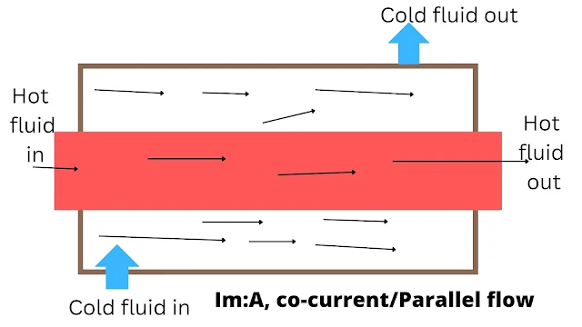
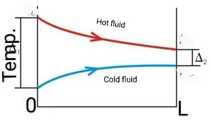
When both fluids flow in the same direction from one end of a heat exchanger to another end through the heat exchanger, then the flow is called co-current or parallel flow. Such a flow is shown in image A. The temperature-length curve for parallel flow arrangements is shown in B.
{tocify} $title={Table of Contents}
When fluids are flowing through a heat exchanger in opposite directions with respect to each other (i.e, one fluid enters at one of the heat exchangers and the other fluid enters at the opposite end of the heat exchanger) then the flow is termed as counter as counter-current flow. Such a flow arrangement is shown in image C. The temperature length curve for counterflow arrangements is shown in image D.
When fluids are directed at right angles to each other through a heat exchanger, then the flow arrangement is called cross flow.
Types of flow of the heat exchanger
Heat exchangers according to flow pattern:
Parallel flow heat exchanger
It is the one in which two fluid streams enter at one end, flow through in the same direction, and leave at the other end. For example, a double-pipe heat exchanger, shell, and tube heat exchanger can be operated in a parallel flow fashion.
Counter current flow heat exchanger
It is the one in which two fluid streams flow in opposite directions. For example, a double pipe heat exchanger, shell, and tube heat exchanger can be operated in this way.
Cross-flow heat exchanger
It is the one in which one fluid moves through the exchanger at right angles to the flow path of another fluid. For example, plate-fin heat exchangers.
Counter current flow V/S Co-current flow
The temperature gradient in case of parallel flow is maximum at the entrance and continuously decreases towards the exit while the temperature gradient is fairly constant over the length of the heat exchanger in case of counter-current flow. Hence, with counter-current flow arrangement the heat exchanger in case of counter capacity through the exchanger and with the parallel flow, the capacity at exit is much less as compared to that at the exchanger.
With parallel flow arrangement, the lowest temperature theoretically attainable by a hot fluid is that of the outlet temperature of a cold fluid. Under this condition, the log means the temperature difference would be zero, and the heat transfer surface requirement would be infinite. ( Q=U.A ∆T/m, U, and A are finite). With this method (parallel flow) it is not possible to bring the hot fluid temperature below the outlet temperature of the cold fluid and thus has a marked effect on the ability of the heat exchanger to recover heat.
In a parallel flow heat exchanger, heat transfer is restricted by the cold fluid outlet temperature rather than the cold fluid inlet temperature, and hence the counter flow arrangement is very common in heat transfer apparatus.
The parallel flow arrangement is used whenever it is necessary to limit the maximum temperatures of the cooler fluid.
In counter-current flow, it is possible for the cooling liquid to leave at a higher temperature than the heating fluid, and one of the greatest advantages of counter-flow is that it is possible to extract a higher proportion of the heat content of the heating fluid. For the same terminal temperature, it is important to note that the value of the logarithmic mean temperature difference for counterflow is appreciably greater than the value for co-current flow. For the same terminal temperature and same heat load, the heat transfer area required for the counter-flow heat exchanger is less than it is for the parallel-flow heat exchanger. The rate of heat transfer in a counter-current flow heat exchanger is more than in a co-current flow exchanger.
In a counter-current flow arrangement, the temperature difference will show less variation throughout the heat exchanger. In co-current flow, the temperature of the two steams progressively approaches one another. The temperature difference will show more variation throughout the heat exchanger.
Take these Notes is, Orginal Sources: Unit Operations-II, KA Gavhane


